


Refrigerant line sizing – Part I: general principles and liquid lines
The development and design processes of a refrigerating system are commonly focused on the major components of the machine: compressor, condenser, evaporator, and throttling device; sometimes the role of the piping in the efficiency of a vapour compression system is forgotten or simply, neglected. On the other hand, it can be easily demonstrated that a rough sizing of the suction, discharge, and liquid lines can lead to a non-negligible efficiency losses. Therefore, a successful refrigeration system also depends on good piping design.
Since the topic includes several interesting aspects, it will be subdivided in three parts: the first one will introduce the general principles of refrigerating line sizing and then will describe the procedure for the liquid lines, the second part will explain the suction and discharge design procedure, whereas the last one will be devoted to the oil management in refrigerant lines.
As general rule, we can state that proper design of a line for a given refrigerant mass flow rate is the trade off between the initial costs, which raise as the diameter increases, and the run costs that decrease as the diameter increases because the refrigerant pumping power decreases. There are also other important issues directly linked to the piping system; among those, it should ensure the oil return to the compressor, preventing excessive amounts of lubricating oil from being trapped in any part of the system; prevent liquid refrigerant or oil slugs from entering the compressor during operating and idle time. Obviously, the piping system should ensure the proper refrigerant feed to evaporator, and maintain a clean and dry system.
Economics, pressure drop, noise, and oil entrainment establish feasible and recommended design velocities in refrigerant lines, which are listed in the next table.
 The upper limits are linked to economics, pressure drop, and noise whereas the lower ones to oil entrainment and fouling issues. An energetic criterion can be considered to design the piping system; pressure drop in suction and discharge refrigerant lines reduces system efficiency because,as the saturation pressure decreases, the saturation temperature decreases, accordingly. In fact, pressure drop calculations are determined as normal pressure loss associated with a change in saturation temperature of the refrigerant. In order to clarify this point, the next table reports some considerations about the effects of refrigerant pressure drop (saturation temperature drop) on the capacity of an ideal refrigerating system, which operates at a 5 °C saturated evaporator temperature with a 40 °C saturated condensing temperature. Three fluids are compared: R134a, propane (R290), and ammonia (R717); the comparisons are carried out considering the separated effects of suction and discharge pressure drops in terms of volumetric cooling capacity and compressor’s work.
 Data reported in the table permit to highlight the different effects of the pressure drops of the suction and discharge lines; as expected, the volumetric capacity is much more affected by the suction pressure drop since both the cooling capacity and the suction vapour density decrease. The increase of compressor’s work due to the suction and discharge pressure drops is similar for all fluids and it slightly depends from the line location.
The liquid line that connects the condenser and the throttling device needs of different considerations; in this case, the pressure drop does not affect the energy efficiency since the aim of the throttling device is to reduce the pressure from the condensation one to the evaporation one. What has to be avoided in the liquid line is the gas formation (“flashing”) due to the pressure drops; in other words, pressure drop should not be so large as to cause gas formation in the liquid line.
From this overview, it clearly appears that the design of suction and discharge lines is a little bit different from that of the liquid lines; the first one is guided by an energy efficiency criterion while the latter follows technological considerations.
The ASHRAE Handbook – Refrigeration (2006) suggests a complete procedure for refrigerant line sizing including several tables for different halocarbons refrigerants and ammonia. The following paragraphs will describe the liquid line design procedure.
Refrigerating systems are normally designed so that pressure drop in the liquid line from friction is not greater than that corresponding to about a 0.5 to 1 K change in saturation temperature. As described by ASHRAE handbook (2006), liquid subcooling is the only method of overcoming liquid line pressure loss to guarantee liquid at the expansion device in the evaporator. If subcooling is insufficient, flashing occurs in the liquid line and degrades system efficiency. The subcooling can be achieved using part of the condenser as a subcooler; this implies that part of the condenser will be flooded and will operate as a receiver. If a receiver is used to control the refrigerant charge fluctuation during the operation, this components should be fed with saturated liquid from the condenser and, then, it should feed the liquid to the subcooler to achieve the requested subcooling level.
The ASHRAE Handbook (2006) reports different tables to design the liquid lines as a function of the system capacity, refrigerant and tube material, for fixed temperature change of 0.02 K m-1in the case of liquid line and for liquid velocity of 0.5 m s-1 for the receiver to condenser connection lines. The next table illustrates an example of the sizing table for R134a, copper tube; the third column is devoted to the liquid lines, the other refers to suction and discharge lines.
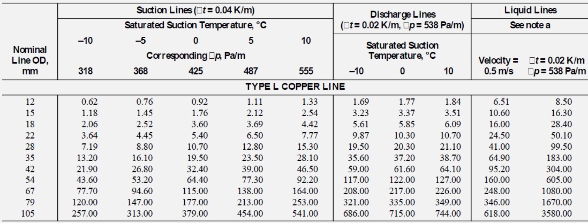 Figure 1: Suction, Discharge, and Liquid Line Capacities in Kilowatts for R134a (Single- or High-Stage Applications). Data estimated
at 40 °C of condensation temperature.
Finally, an additional consideration must be reported: liquid-line risers are a source of pressure loss and add to the total loss of the liquid line. Loss caused by risers is approximately 11.3 kPa per metre of liquid lift. Total loss is the sum of all friction losses plus pressure loss from liquid risers.
The liquid line design procedure is the following: using the system capacity and the proper tablefor the considered fluid (see Figure 1), the nominal line diameter is determined. Then, the total equivalent length Le from condenser to throttling device or from receiver to subcooler must be estimated, this value is the sum of the straight pipe length and the equivalent length for fitting (elbows, contraction, etc.). The equivalent lengths for fitting are listed in special tables reported by ASHRAE handbook (2006). Now, the actual temperature drop ΔT can be calculated as:
![]()
Where (ΔT/L)Table is the design temperature drop per unit of length, P0 is the cooling capacity and P0,Table is the cooling capacity listed in the table. The tables refer to 40°C condensation temperature, for other saturation temperatures, a correction factor must be applied. If there are some risers the additional pressure drops must be accounted and then the total pressure drop can be calculated. Considering the condensation pressure, it is possible to calculate the final pressure at the inlet of the throttling device and verify if the subcooling is enough to avoid the gas formation. The following examples explain the use of the tables for liquid line sizing. A R134a refrigeration system using copper pipe operates at 5 °C evaporator and 40 °C condensing. Capacity is 20 kW and the liquid line is 50 m equivalent length without riser. Determine liquid line size. Considering the table reported in Figure 1, last column, since the actual capacity is 20 kW, the nominal diameter can be 15 mm (P0,Table=16.30 kW) or 18 mm (P0,Table=28.40 kW). The temperature drops can be calculated with the previous equations:

with 15 mm tube, the temperature drop is greater than 1 K, thus it is not acceptable, the proper design of this liquid line calls for 18 mm nominal tube diameter. If the same system included a riser of 4 m, the design procedure should also account for this additional pressure drop:
Δpr= 11,3 ・L = 11.3 ・4= 45.2 kPa=45200 Pa
The frictional pressure drop can be calculated as:
Δpf= (Δp/L)Table・ L= 538・50 = 26900Pa=26.90 kPa
The total pressure drop is given by the sum of these values as,
Δptot=Δpr+Δpf=45.2+26.90=72.10 kPa = 72100Pa.
The saturation pressure of the R134a at 40°C is 1016.6kPa, thus the net pressure at the inlet of the expansion device is:
P=Psat-Δptot=1016.6-72.10=944.5kPa=944500Pa. This pressure corresponds to 37.28 °C of saturation temperature, this means that the refrigerant at the inlet of the liquid line must be at least 2.72 K subcooled to obtain saturated liquid at the inlet of the throttling device; however, 3-4 K of subcooling are preferable.
References
ASHRAE Handbook, Refrigeration, 2006.


