


Refrigerant line sizing – Part II: suction and discharge lines
This second part describes the design procedure of the suction and discharge lines according to what suggested by ASHRAE Handbook (2006). Suction and discharge lines are more critical than liquid ones from a design and construction standpoint. Besides, suction lines are even more critical than discharge ones. Refrigerant lines should be sized to provide a minimum pressure drop at full load, return oil from the evaporator to the compressor under minimum load conditions, and prevent oil draining from an active evaporator into an idle one. As outlined in Part I, the pressure drop in the suction line reduces the system’s capacity because it forces the compressor to operate at a lower suction pressure to maintain a desired
evaporating temperature in the evaporator. The suction and discharge lines are normally sized to have a total pressure drop no greater than the equivalent of about a 1 K change in saturation temperature. For a given refrigerant mass flow rate and a temperature drop per unit of length, discharge lines are smaller than suctionones because the vapour density is higher and the saturation temperature drop for a given pressure
drop is smaller. Therefore, the temperature drop per unit of length for suction lines is greater than that of discharge ones. The tables suggested by ASHRAE Handbook (2006) for halocarbon refrigerants are based on 0.02 K/m for the discharge lines and 0.04 K/m for the suction lines. In the case of ammonia the temperature drop per unit of length is usually taken as half of the previous values. The tables report the recommended nominal diameter for given refrigerant and application as a function of the system capacity. The data listed in tables refer to a refrigerating system which operates at 40 °C of condensation temperature without subcooling, but they can be applied up to 5 K of subcooling without introducing any
appreciable error. The next figures report two examples of the tables as proposed by ASHRAE Handbook (2006) for copper tubes; similar tables are proposed for steel lines.
![]()
Figure 1: Suction, Discharge, and Liquid Line Capacities in Kilowatts for R134a (Single- or High-Stage Applications)
![]()
Figure 2: Suction, Discharge, and Liquid Line Capacities in Kilowatts for R410A (Single- or High-Stage Applications).
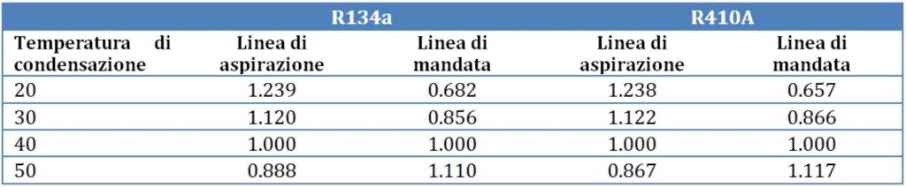
For different condensation temperature the table capacities must be multiplied by the correction factors listed, which depend on the selected refrigerant. The following values of correction factors are relative to the tables reported in Figures 1 and 2.
The design procedure can be summarized as follows: first of all, for a given cooling capacity and refrigerant, the previous Tables permit to find out the recommended pipe diameter (for 40 °C of condensation temperature); then the total equivalent length of tube must be estimated, it is the sum of the straight pipe length and the equivalent length of fittings, which can be obtained from Table similar to that reported in
Figure 3.
as a subcooler; this implies that part of the condenser will be flooded and will operate as a receiver. If a receiver is used to control the refrigerant charge fluctuation during the operation, this components should be fed with saturated liquid from the condenser and, then, it should feed the liquid to the subcooler to achieve the requested subcooling level.
The ASHRAE Handbook (2006) reports different tables to design the liquid lines as a function of the system capacity, refrigerant and tube material, for fixed temperature change of 0.02 K m-1in the case of liquid line and for liquid velocity of 0.5 m s-1 for the receiver to condenser connection lines. The next table illustrates an example of the sizing table for R134a, copper tube; the third column is devoted to the liquid lines, the other refers to suction and discharge lines.
![]()
Figure 3: Fitting Losses in Equivalent Metres of Pipe.
Once that the equivalent lengthLe is known, the total temperature drop ΔT can be easily estimated using the following equation:
![]()
where (ΔT/L)Table is the design temperature drop per unit of length, P0 is the cooling capacity and P0,Table is the cooling capacity listed in the table. If this value is lower than 1 K, the line is sized; otherwise, a little bit bigger tube should be selected.
The following examples permit to clarify the design procedure. Determine the suction and discharge line sizes of a 130 kW R410A refrigerating system operating at 5 °C suction and 40 °C of condensing temperatures. The suction line consists of Lt=15 m of straight tube with 8 long radius elbows while the discharge line consists of 15 m with 10 standard elbows. Then, determine the lines’ sizes if the condensation temperature becomes 50 °C.
Suction From Figure 2, 191.84 kW capacity in 54 mm OD suction line results in a 0.04 K m-1. Thus, from Figure 3, a 50 mm long radius elbow has a equivalent length of Lf=1.0 m. The total equivalent length can be easily calculated:
![]()
using the previous equation, it is possible to estimate the temperature drop in the suction line:
![]()
Recompute for the next smaller, 42 mm OD tube, the equivalent length for the elbows becomes Lf=0.8 m and the total equivalent length Le=21.4 m, then the temperature drop becomes 1.45 K, which is slightly higher than 1K. Therefore, the 54 mm tube is recommended.
Discharge From Figure 2, 139.76 kW capacity in 42 mm OD suction line results in a 0.02 K m-1; from Figure 3, a 40 mm standard elbow has a equivalent length of Lf=1.2 m. The total equivalent length is Le=27 m. The temperature drop associated is 0.47 K, which is lower than 1 K.
If the condensation temperature becomes 50 °C, the values listed in Figures 1 and 2 must be corrected using the correction factors listed in the table.
Suction The correction factor is 0.867, thus the 54 mm OD tube, which at 40 °C has a capacity of 191.84 kW, now it has a capacity of:
![]() This capacity is higher that 130 kW, thus 54 mm can be selected, the temperature drop associated to the equivalent length of Le=23.0 m is 0.59 K(acceptable).
This capacity is higher that 130 kW, thus 54 mm can be selected, the temperature drop associated to the equivalent length of Le=23.0 m is 0.59 K(acceptable).
Discharge The correction factor for discharge lines is 1.117; thus, the previous 139.76 kW associated to 42 mm OD tube becomes 156.11 kW that with an equivalent length of Le=27 m implies a temperature drop of 0.39 K (acceptable).
References
ASHRAE Handbook, Refrigeration, 2006.


