


Evaporators and condensers: counter-current or co-current arrangement?
The proper selection between counter-current and co-current flow arrangements in heat exchangers is often reason for discussion and debates, and if the heat exchanger is a condenser or an evaporator, the discussion becomes a clash between two opposite supporters.
Before talking about what is the most rational choice, it’s useful to recall that the heat flow rate q exchanged in a heat exchanger of known geometry, can be calculated using the following equation:
![]()
where A is the heat transfer area, K is the overall heat transfer coefficient, while ∆Tm is the mean temperature difference properly calculated. The two classical flow arrangements are displayed in the figure below: the hot fluid (H) in red, and the cold one (C) in blue. As you can see, the temperature difference changes continuously throughout the heat exchanger; for this reason, the selection of a mean value must be carefully done.
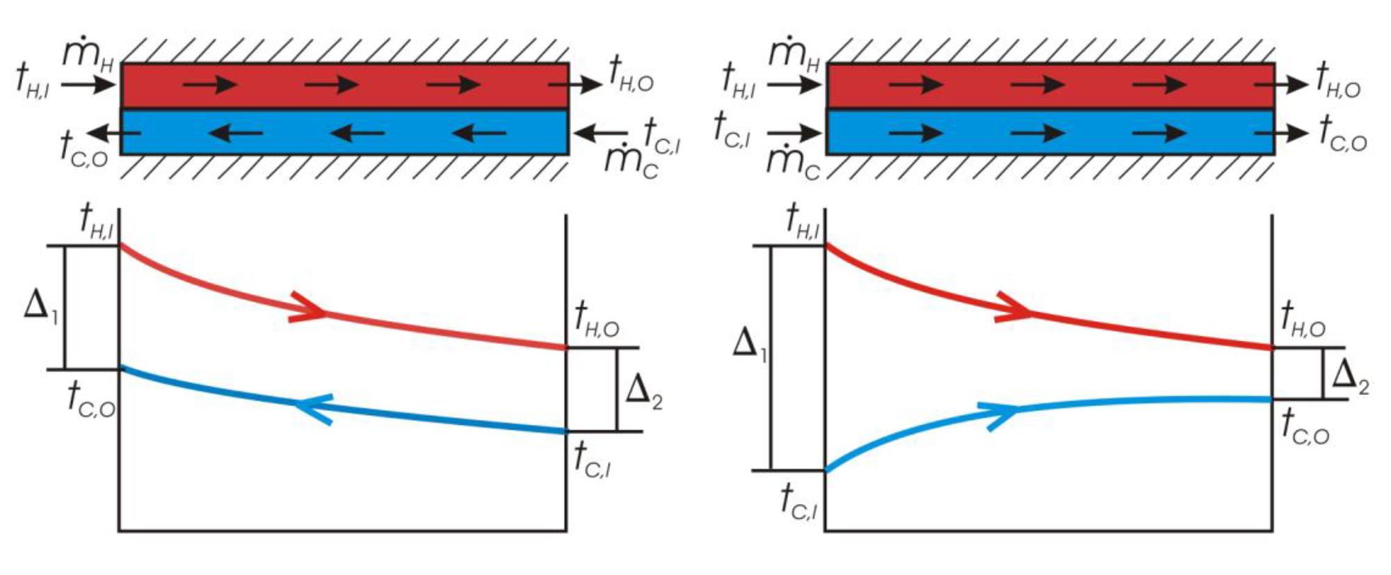
Counter-current and co-current flow arrangements for a heat exchanger.
Avoiding the mathematical procedure, it is possible to demonstrate that under certain hypotheses, the logarithmic mean temperature difference is a good method for the estimation of the total heat flow rate exchanged in a heat exchanger. Its value can be calculated from the temperatures at the inlet and outlet sides of the heat exchanger, as showed in the figure and defined by the following equation:

It’s easy to demonstrate that, in the case of mono-phase heat exchange, if you keep constant the mass flow rates and the inlet and outlet temperatures of the fluids, the counter-current arrangement gives always better values of logarithmic mean temperature difference (See table below). Therefore, for the same heat flow rate q, geometry and operating conditions, the heat transfer required area will result less in a counter-current configuration. Furthermore, considering the temperature profiles, in counter-current flow, the outlet temperature of a fluid can hypothetically reach the inlet temperature of the other fluid. In the co-current flow, this is not possible since the temperatures of the two fluids evolve together. (See figure above)
![]()
Considering the case of heat exchangers where condensation or evaporation processes happens, one can remain astonished because the calculated values of logarithmic mean temperature difference for each transformation, for both flow arrangements, are actually he same. (See table below)
The next figure shows the temperature profiles of the two transformations, without considering any pressure drops effect and refrigerant superheating/subcooling.

Condensation and evaporation temperature profiles for a pure refrigerant.
The following table shows what mentioned above: in the two operating conditions, the values of logarithmic mean temperature difference both in counter-current and co-current configurations are the same. Thus, which is the best arrangement that should be chosen, and why?

The method of the logarithmic mean temperature difference analyzes the overall behavior of a heat exchanger and it’s based on several assumptions that, in the real world, may not always be valid.
Considering first the condensation process, even ignoring pressure drops, the counter-flow configuration is always the best choice. The heat transfer coefficient () decreases as the condensation process proceeds, i.e. as the vapor quality decreases. As highlighted in the figure, it is convenient to select the counter-flow configuration in order to compensate low values of heat transfer coefficient with high values of temperature difference. In the same figure, the temperature profiles in presence of pressure drops effect are shown: again the counter-current arrangement permits to shift the temperature penalization where the temperature differences are higher, improving the final heat transfer.

Condenser: temperature profiles without pressure drops (continuous line) and with pressure drops (dotted line).
Considering the evaporator (ignoring any superheating), we obtain opposite conclusions; in fact, it is possible to demonstrate that the flow configuration which would improve the heat transfer, is the co-current one.

Evaporator with superheating: temperature profiles without pressure drops (continuous line) and with pressure drops (dot line).
On the other hand, in the case of dry expansion evaporators, the vapor at the outlet side of the heat exchanger must be superheated at least 5°C; this condition alters the conclusions just outlined. The superheating process is characterized by low values of heat transfer coefficients, and for this reason it is recommended to associate this region to the highest values of temperature difference: this is possible only using a counter-flow arrangement. In co-current configuration, the two temperature profiles tend to the same value and the heat exchanger would have a part with low heat transfer efficiency characterized by low heat transfer coefficients and low temperature differences. This explains the universally accepted designing rule for dry expansion evaporators, which suggest the counter-current arrangement as the best choice.
Correlated topics
- The role of the distributor in dry expansion evaporators
- The condensation from superheated: when does it start?
- Condensation inside microfin tubes: the selection of the optimum mass flow rate


