


Refrigerant line sizing – Part III: oil management in refrigerant lines
All refrigerant systems host a certain amount of oil used to lubricate the compressor, cool the electrical windings, etc. On the other hand, it is well known that all compressors lose some lubricating oil during normal operation. Because oil inevitably leaves the compressor with the discharge gas, systems using halocarbon refrigerants must return this oil at the same rate at which it leaves. Except for most centrifugal compressors and rarely used non-lubricated compressors, refrigerant continuously carries oil into the discharge line from the compressor. To reduce the amount of circulating oil, separators can be implemented in the system; unfortunately, they are not 100% effective. Oil that finds its way into the system must be managed.In fact, oil that leaves the compressor or oil separator enters in the condenser and dissolves in the liquid refrigerant;the liquid mixturereadily passes through the liquid line to the evaporator. In the evaporator, the refrigerant evaporates, and the liquid phase becomes enriched in oil. The concentration of refrigerant in the oil depends on the evaporator temperature and types of refrigerant and oil used. The viscosity of the oil/refrigerant solution is determined by the system parameters. Oil separated in the evaporator is returned to the compressor by gravity or by drag forces of the returning gas.
The oil return problem involves both the direct expansion and flooded evaporators but different considerations must be outlined. One of the most difficult issues in low-temperature refrigeration systems using halocarbon refrigerants is returning lubrication oil from the flooded evaporator to the compressors. This is because oil mixes well with halocarbon refrigerants at higher temperatures. As temperature decreases, miscibility is reduced, and some oil separates to form an oil-rich layer near the top of the liquid level in a flooded evaporator. Thus, flooded evaporators can promote oil contamination of the evaporator charge because they may only return dry refrigerant vapour back to the system. If the temperature is very low, the oil becomes a gummy mass that prevents refrigerant controls from functioning, blocks flow passages, and fouls heat transfer surfaces.
The oil return problem involves both the direct expansion and flooded evaporators but different considerations must be outlined. One of the most difficult issues in low-temperature refrigeration systems using halocarbon refrigerants is returning lubrication oil from the flooded evaporator to the compressors. This is because oil mixes well with halocarbon refrigerants at higher temperatures. As temperature decreases, miscibility is reduced, and some oil separates to form an oil-rich layer near the top of the liquid level in a flooded evaporator. Thus, flooded evaporators can promote oil contamination of the evaporator charge because they may only return dry refrigerant vapour back to the system. If the temperature is very low, the oil becomes a gummy mass that prevents refrigerant controls from functioning, blocks flow passages, and fouls heat transfer surfaces.
The previous newsletters discussed the design procedures for liquid, suction and discharge lines based on energy criteria; the lines sized in such way can sometimes be unable to ensure the proper oil return to compressors. All the lines are sized under full load conditions but the refrigerating system can run most of time in part load conditions. The compressor can load and unload as it modulates with system load requirements through a considerable range of capacity. A single compressor can unload down to 25% of full-load capacity, and multiple compressors connected in parallel can unload to a system capacity of 12.5% or lower. As an outcome, system piping must be designed to return oil at the lowest loading, yet not impose excessive pressure drops in the piping and equipment at full load.
Two lines are critical from the oil return standpoint: the suction line and the discharge one(also named hot gas line). Therefore, these two lines must be verified for oil return in part load operation; the check is only necessary for risers with upward flow because the other lines are usually downward positioned and tilted of about 0.5% to exploit the gravity force.
Considering the suction lines, many refrigeration piping systems contain a suction riser because the evaporator is at a lower level than the compressor. Oil circulating in the system can return up gas risers only by being transported by returning gas or by auxiliary means such as a trap and pump.Hot-gas lines should be designed to: avoid trapping oil at part-load operation, prevent condensed refrigerant and oil in the line from draining back to the head of the compressor, avoid developing excessive noise or vibration from hot-gas pulsations, compressor vibration, or both.
The minimum conditions for oil transport correlate with buoyancy forces (i.e., density difference between liquid and vapour, and momentum flux of vapour).The principal criteria determining the transport of oil are gas velocity, gas density, and pipe inside diameter. Density of the oil/ refrigerant mixture plays a somewhat lesser role because it is almost constant over a wide range. Of course, the critical conditions for the suction and discharge lines are different but the criterion and the check procedure is the same.
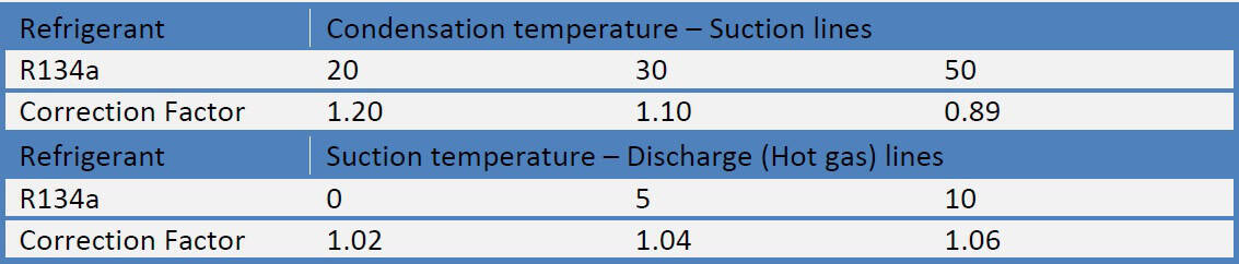
Figure 1 reports a table suggested by ASHRAE – Handbook (2006), which translates these criteria to minimum refrigeration capacity requirements for oil transport in suction risers. Oil must be returned to the compressor at the operating condition corresponding to the minimum displacement and minimum suction temperature at which the compressor will operate. The table is based on condensing temperature of 40 °C, for other liquid line temperatures, correction factors are suggested (see table below); the values are computed using ISO32 ester-based oil.

Figure 1: Minimum Refrigeration Capacity in Kilowatts for Oil Entrainment up Suction Risers. R134a
Figure 2 reports a Table proposed by ASHRAE – Handbook (2006) that lists the minimum capacities for oil entrainment in hot-gas line risers for R134a. The values are calculated using ISO32 ester-based oil at -5 °C of evaporating temperature; for other suction temperatures, correction factors must be considered (see table below).
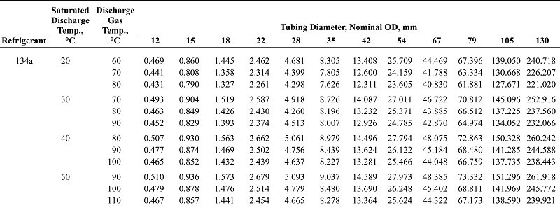
Figure 2: Minimum Refrigeration Capacity in Kilowatts for Oil Entrainment up Hot-Gas Risers. R134a
The following example explains the use of the two Tables reported in Figure 1 and 2. Determine the maximum sizes of suction and hot gas risers that will transport oil at minimum loading, using R134a with a 130 kW compressor with capacity steps of 25%, 50%,75%, and 100%. Considering a suction temperature of 5 °C with 15 K of superheating and 40 °C of condensing temperature. Suction line: equivalent length of 20 m with a riser. Discharge line: equivalent length of 25 m with a riser.
First of all, according to what described in the previous newsletter: “Refrigerant line sizing – Part II: suction and discharge lines”, the suction and discharge lines must be sized. From the proposed table for suction line sizing, for a capacity of 130 kW (full-load), a 67 mm OD tube is recommended, the temperature drop associated is 0.72 K that is acceptable.Following the same procedure with the proper table, a 54 mm OD pipe for the discharge line presents a temperature drop of 0.54 K that is acceptable. Considering the oil return up to suction riser, the minimum capacity of this system is the 25% of the full load:
Po,min= P0 ・0,25= 32,5 kW
According to Figure 1, a 67 mm OD tube at 5°C and 15 K of superheating has a minimum capacity of 31.79 kW, which is slightly lower than the calculated cooling capacity of the system. The suction line is well designed. Considering the hot-gas line, according to Figure 2, a 54 mm OD tube at 40 °C of condensation temperature has a minimum capacity of 27.79 kW (worst case) which is lower than the 25% of the full load. The hot gas line is well designed.
In this example, the suction line sized using the energy criterion permits the oil return to compressor but sometimes two different diameter must be selected to cover all the system capacities. When the suction riser is sized to allow oil return at the minimum operating capacity of the system, pressure drop in this portion of the line may be too great when operating at full load. If a correctly sized suction riser imposes too great a pressure drop at full load, a double suction riser should be used. An example of the double suction riser is plotted in Figure 3.

The riser A is sized to return oil at minimum load possible while Riser is sized for satisfactory pressure drop through both risers at full load. A trap is introduced between the two risers; during part-load operation, gas velocity is not sufficient to return oil through both risers, and the trap gradually fills up with oil until riser B is sealed off. The gas then travels up riser A only with enough velocity to carry oil along with it back into the horizontal suction main. At full load, the gas pushed away through the pipe the oil trapped in the bend enabling both risers.
References
ASHRAE Handbook, Refrigeration, 2006.
Correlated topics:
- Refrigerant line sizing – Part I: general principles and liquid lines.
- Il dimensionamento delle tubazioni di un circuito frigorifero – Parte II: linee di aspirazione e mandata
- How to design a capillary tube: the simplest and most reliable throttling device


