


Heat Pipes – Part II Operating principles: capillary pumping pressure
In a previous article, “Heat Pipes – Part I: from aerospace to air conditioning applications”, we introduced and described, from a general point of view, the Heat Pipes and Thermosyphon. Now, we want to present some general aspects concerning on the operating principles of these devices.
As already stated, a heat pipe is a high heat flux, passive heat transfer device, which uses evaporation, condensation and surface tension of the operating fluid to achieve extremely high thermal conduction.

Figure 1: Schematic of a heat pipe.
As shown in Figure 1, a heat pipe can be subdivided in three main regions: the evaporator zone, the adiabatic zone, and the condenser zone. The container is internally lined with a capillary structure which is saturated with the liquid phase of the heat transfer fluid. Upon heating one end of the container the liquid retracts into the capillary structure. The generated vapour flows toward the cold end of the container where it condenses and fills the capillary structure. The difference in the liquid filling heights in the structure causes a capillary force that sucks the liquid back to the evaporator.
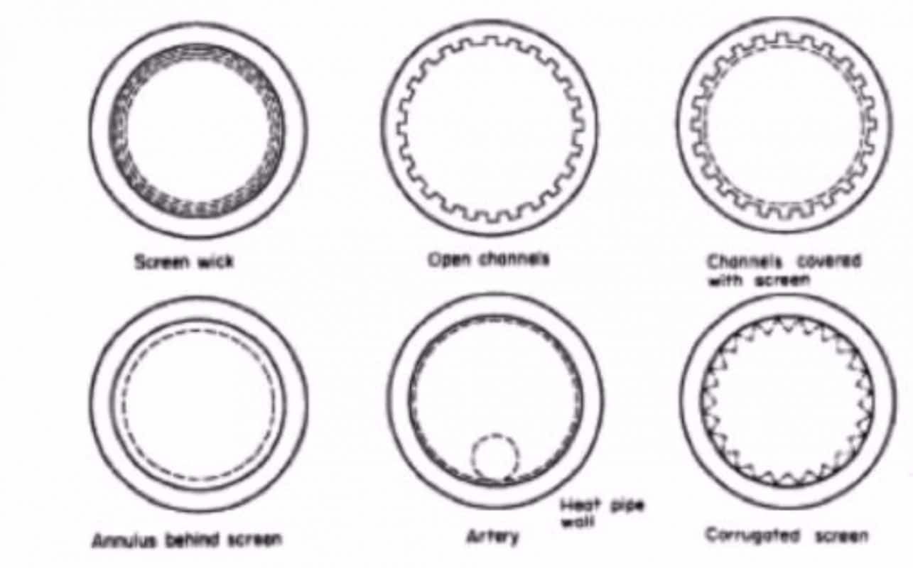
Figure 2: Different capillary structures (from left-top corner):
mesh or sintered structure, open axial grooves, annulus under screen, artery, corrugated.
In order for the heat pipe to operate the maximum capillary pumping pressure, ![]() must be greater than the total pressure drop in the pipe. This pressure drop is made up of three components:
must be greater than the total pressure drop in the pipe. This pressure drop is made up of three components:
- The pressure drop
 required to return the liquid from the condenser to the evaporator.
 - The pressure drop
 necessary to cause the vapour to flow from the evaporator to the condenser.
 - The pressure due to the gravitational head,
 which may be zero, positive or negative, depending on the inclination of the heat pipe.
Thus, for correct operation,
![]()
The capillary pumping pressure is equal to the difference between the capillary pressure Pc,evap at the evaporator end and the the capillary pressure Pc,cond at the condenser,
![]()
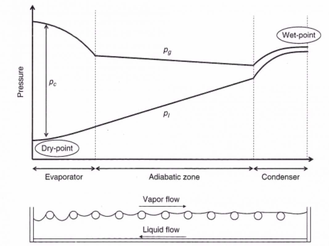
Figure 3: Pressure profiles along the heat pipe.
Figure 3 shows the capillary pressure Pc along the heat pipe, as clearly appears, the maximum capillary pumping pressure is achieved when the Pc,evap is maximal and Pc,condbecomes minimal; thus, when the condenser capillary structure is flooded with liquid, and the capillary pressure at this end tends to zero.
The maximum capillary pumping power is given by:
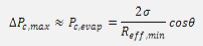
where ![]() is the surface tension of the liquid, Reff,min is the minimum curvature radius at the evaporator end, and
is the surface tension of the liquid, Reff,min is the minimum curvature radius at the evaporator end, and ![]() is the macroscopically apparent contact angle, which depends on the fluid/capillary structure combination, the surface roughness, the surface state, and the local heat flux. Anyway, if accurate and reliable data for are not available, some indicative values can be: water
is the macroscopically apparent contact angle, which depends on the fluid/capillary structure combination, the surface roughness, the surface state, and the local heat flux. Anyway, if accurate and reliable data for are not available, some indicative values can be: water ![]() =40°-45°, hydrocarbons
=40°-45°, hydrocarbons ![]() =35°, ammonia
=35°, ammonia ![]() =20°-25°.
=20°-25°.
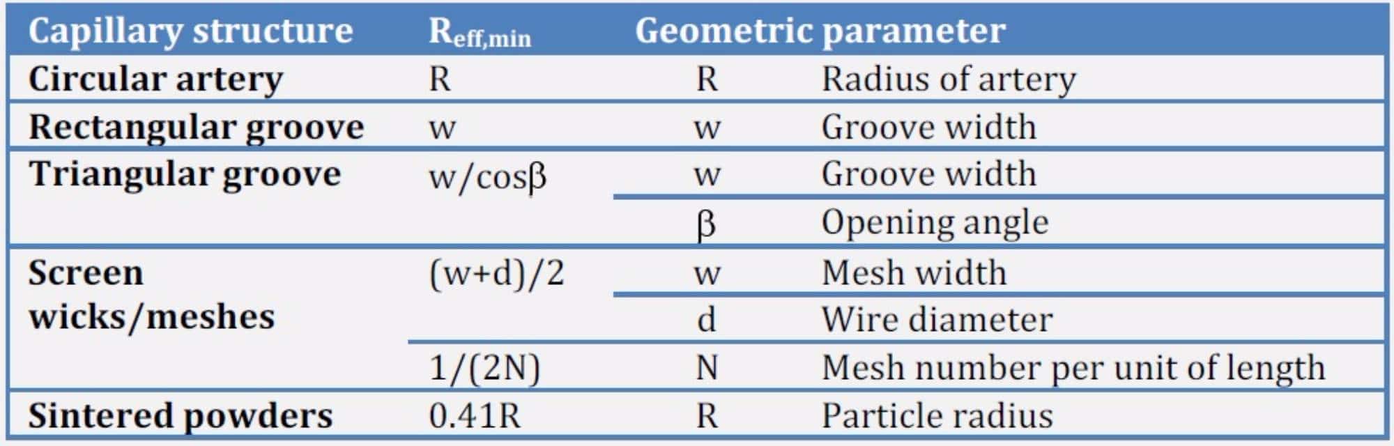
The capillary structure also controls the values of Reff,min, which for different configurations must be defined; the next Table lists some of this values.
From this brief overview, it is demonstrated that the selection of the fluid/capillary structure combination controls the operation of the heat pipe, thus must be chosen properly. The next numerical example explains the effect of the fluid selection on the maximum capillary pumping pressure achievable for a given capillary structure.
Determine the maximum capillary pumping pressure generated in a heat pipe operating at a saturation temperature of 10°C, made of an aluminum tube with 32 axial open grooves (w=0.5 mm and h=0.8 mm) when filled up with water, ammonia or methanol.
The Reff,min is selected according to the previous Table equal to the groove width, w=0.5 mm. The values of surface tension of the three fluids at 10°C of saturation temperature are: 74.221 mN/m, 29.589 mN/m, and 23.505 mN/m for water, ammonia, and methanol, respectively.
Finally, the macroscopically apparent contact angles can be selected as: water ![]() =45°, methanol
=45°, methanol ![]() =35°, ammonia
=35°, ammonia ![]() =25°.
=25°.
Thus the three different maximum capillary pumping pressure values are given by:
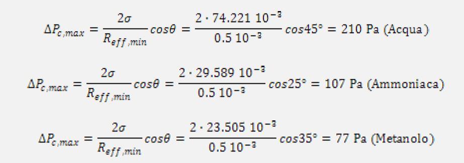
It is shown that the pairing water/capillary structure generates the highest capillary pumping pressure; the pairing Ammonia/capillary structure shows a capillary pumping pressure almost half than that obtained for water. However, water cannot be used under 0 °C. Another interesting example permits to highlight the effect of the capillary structure on the maximum capillary pumping pressure.
Determine the maximum capillary pumping pressure exploited by ammonia at 10 °C, which fills up sintered wick structures obtained from powders with different particles radii: 100, 200, and 300 m.
The smallest particle exhibits the highest theoretical capillary pumping pressure, that is:
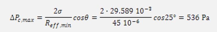
when the particle radius becomes 200 ![]() , the capillary pumping pressure is 268 Pa, and then for R=300
, the capillary pumping pressure is 268 Pa, and then for R=300 ![]() ,
, ![]() =195 Pa. As the particle radius decreases, the capillary pumping pressure increases, which is always higher than that calculated for the axially grooved capillary structure.
=195 Pa. As the particle radius decreases, the capillary pumping pressure increases, which is always higher than that calculated for the axially grooved capillary structure.
The maximum capillary pumping pressure must be greater or at least equal to the total pressure drop as described before; thus, proper correlations for the liquid and vapour pressure drops inside the heat pipe must be selected for each capillary structure in order to correctly evaluate their values.
References
- G.P. Paterson, An introduction to heat pipes. Modeling, Testing, and Applications, Ed. John Wiley and Sons, 1994, New York, USA.
- D. Reay, P. Kew, Heat Pipes – Theory, Design and Applications, 5th ed., Ed. Elsevier, 2006, Burlington, MA , USA
- P. Stephan, Heat Pipes, N5 VDI
Correlated topics
- What are nanofluids and which are their applications?
- Heat Pipes – Part III: Operating principles: heat transfer limits
- Wraparound Heat Pipes for air conditioning applications


