


Carbon dioxide heat pump: from the condenser to the gas-cooler
As already underlined (newsletter no. 1 – October 2012 “Carbon Dioxide as refrigerant”), the carbon dioxide shows interesting thermophysical properties and it is an eco-friendly natural refrigerant. These characteristics make it a suitable alternative to the synthetic refrigerants.
The common applications of CO2 regard the low-temperatures, where it has been applied since ‘900s; furthermore, we cannot forget the automotive air conditioning that, after the statement issued by one the biggest cars’ manufacturers concerning the safety risks associated to the flammability of R1234yf, will become an interesting research field.
Other possible applications of the CO2 as working fluid regard the water heating heat pumps for sanitary uses, space heating with radiant panels or low-temperature fan coils. In order to understand why the carbon dioxide seems to be a good refrigerant for this kind of machines, several considerations relative to its thermophysical properties and how those vary with pressure and temperature have to be discussed.
In a previous newsletter (newsletter no. 6 – February 2013 “What happens to fluid properties near the critical point? The case of CO2”), it was highlighted that for CO2 the critical point is characterized by a temperature of 30.978 °C and by a pressure of 73.773 bar. This fact strongly affects its thermophysical properties and it also affects the thermodynamic cycles that can be implemented in heating and cooling systems.
In the common refrigeration technology, a refrigeration system consists of four main components: a compressor, a condenser, a throttling device, and an evaporator. In order to use the carbon dioxide as working fluid in a such system, it has to be pointed out that at 40-50 °C (common condensation level for refrigeration systems) it is gaseous, so that, a condenser cannot be used to reject the heat.
The condenser has to be substituted by a gas-cooler, where the carbon dioxide will be cooled without any phase change process. Figure 1 reports a typical transcritical cycle on a T-h plot.
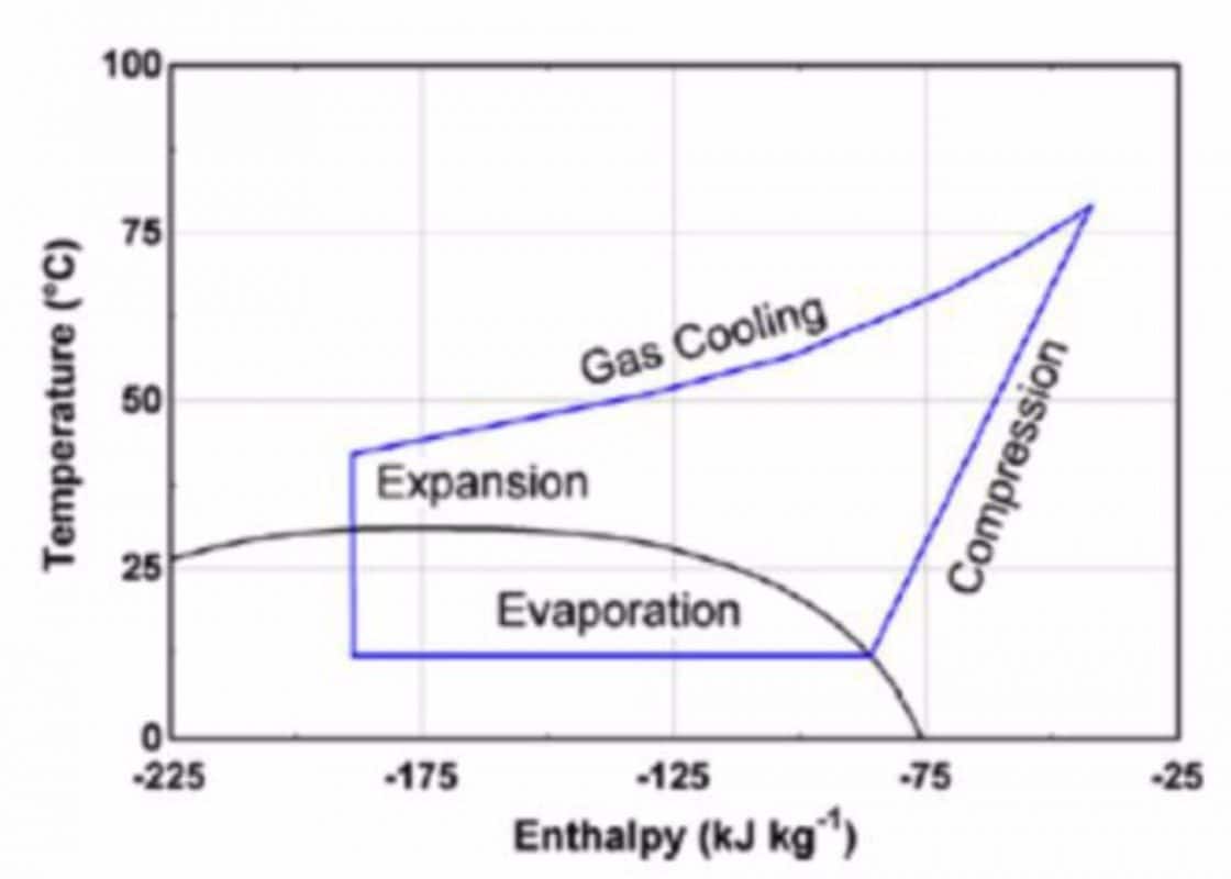
Figure 1: Transcritical cycle for CO2 plotted on a T-h plot. (Fronk and Garimella, 2011)
At first sight, it also appears that during the cooling process, the carbon dioxide approaches the critical point where its thermophysical properties suddenly change; this characteristic cannot be neglected during the design of gas-coolers without incurring in unmanageable errors.
Figure 2 shows water being heated by CO2 and R134a. A pinch effect is observed in the R134a case, when a water outlet temperature of 70 °C is desired. Increasing the high-side pressure of the R134a system would allow higher water delivery temperatures; however, the corresponding narrowing of the vapor dome and increased pressure ratio would be detrimental to system performance. The temperature profile of the CO2, on the other hand, matches well with the high temperature lift required by the water. This evidence highlights, one more time, the interesting characteristics of the transcritical cycle for water heating applications.
The gas-cooler requires special design considerations due to the high operating temperature and the temperature glide during supercritical cooling of CO2. To achieve maximum system COP, the gas-cooler must be designed in such a way as to minimize the approach temperature between the heat sink and refrigerant.
The large variations of the thermophysical properties in region close to the critical point affect both the method to estimate the heat exchanged and the evaluation of the heat transfer coefficient, which strongly varies throughout the heat transfer process.
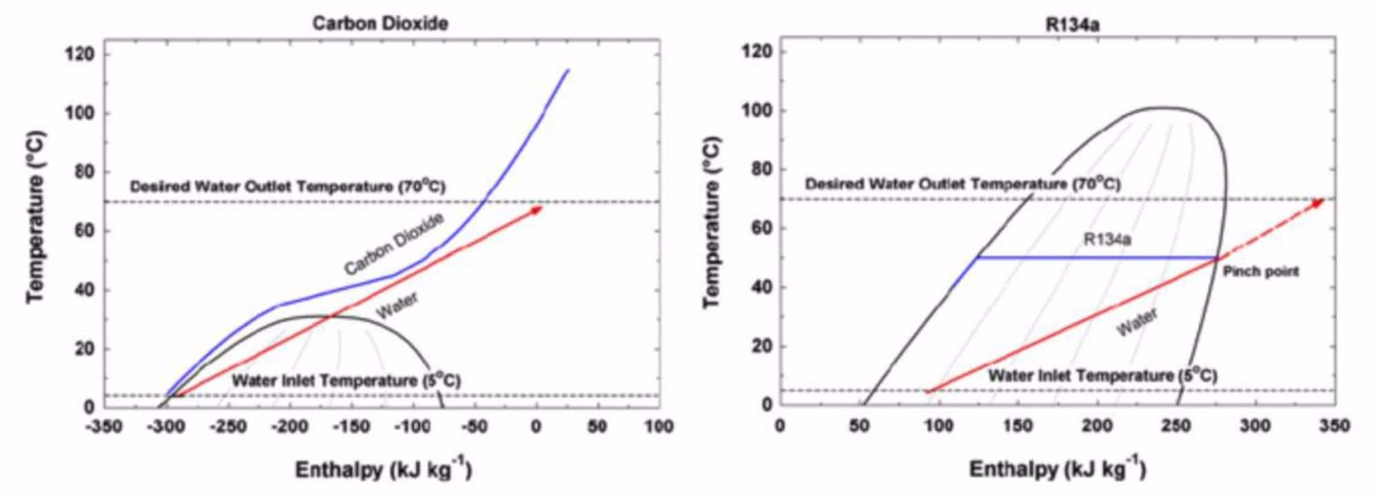
Figure 2: CO2 vs. R134a temperature pinch effect. (Fronk and Garimella, 2011)
As highlighted in Figure 3, the heat transfer coefficient presents different peaks located at the pseudocritical temperature as a function of the pressure; the closer is the pressure to the critical one, the higher is the heat transfer coefficient’s peak.
The values reported in Figure 3 are calculated using the model proposed by Dang and Hihara (2004); this correlation accurately reconstructs the real behavior of carbon dioxide during the gas cooling process.

Figure 3: Carbon dioxide heat transfer coefficient during the gas cooling process as a function of the operative pressure.
The gas cooling process starts when the discharged hot gases at the outlet of the compressor enter the gas-cooler; for sake of clarity, considering two pressure levels 80 bar and 100 bar, at these pressures the end compressor temperatures are usually around 80-85 °C and 120-125 °C, respectively. Following the gas cooling process, it clearly appears how the heat transfer coefficient rises up to a peak and then decreases: at 80 bar, the heat transfer coefficient is initially equal to 2000 W m-2 K-1 but, then, it rises up to 13500 W m-2 K-1; at 100 bar, the increasing is less, however, the maximum heat transfer coefficient is 3 times higher than that at the inlet of the gas-cooler.
Such high variation of the heat transfer coefficient implies that it is not possible to design the heat exchanger using the common general approach (for instance, logarithmic mean temperature difference) because it would lead to incorrect values of the total heat exchanged in the heat exchanger.
A detailed model must be implemented because it allows for a better control of the effective heat exchanged in each sector of the gas-cooler.
Figure 4 (left-side) shows a traditional coil, which is subdivided in two sectors: the first one, named intercooler, is used to cool down the hot CO2 gas between the first and the second stage of compression; the second sector is the actual gas-cooler’s part. Nowadays, the optimization of the gas-coolers is accomplished using aluminum microchannel heat exchangers, which also improve the air-side heat transfer capabilities.

Figure 4: An example of a traditional gas-cooler (left) and an example of a microchannel gas-cooler (right).
A schematic of a microchannel heat exchanger is reported in Figure 4 (right-side). Brazed plate heat exchanger and tube-in-tube heat exchangers are commonly used in the water heating heat pumps for sanitary and space heating applications. Recently, as it is shown in Figure 5, as innovative and compact gas-cooler has been developed by Fronk and Garimella (2011); in this prototype, the plate and microchannel heat exchangers’ concepts merge together in a novel heat exchanger.

Figure 5: New concept of gas-cooler. (Fronk and Garimella, 2011)
References
A. Cavallini, D. Del Col, L. Doretti, C. Zilio, I fluidi frigorigeni processi di sostituzione e nuove frontiere tecnologiche, 2007, n. 26, Progetto Novimpresa, AREA Science Park, Trieste, Italia.
C. Dang, E. Hihara, In-tube cooling heat transfer of supercritical carbon dioxide. Part 1. Experimental measurement, International Journal of Refrigeration, 27(7) (2004) 736–747
B. M. Fronk, S. Garimella, Water-coupled carbon dioxide microchannel gas cooler for heat pump water heaters: Part I – Experiments, International Journal of Refrigeration 34 (2011) 7-16.
Correlated topics
Carbon Dioxide as refrigerant
What happens to fluid properties near the critical point? The case of CO2
Transcritical cycle for refrigerating application: the optimum pressure.


