


Microfin tubes: are those always necessary and convenient?
In order to reduce both the refrigerant charge and the volume of machinery, the refrigeration and air conditioning manufactures design their heat exchangers with enhanced surfaces. In fact, since the Fujie et al. (1977) invention, microfin tubes have received increasing attention because of the fact that they ensure a large heat transfer enhancement (80‐180%) when compared to equivalent smooth tubes under the same operating conditions, with a relatively small increase in pressure drop (20‐80%).
In the last thirty years, this technology has been largely investigated: many experimental and theoretical studies have been conducted and several models have been presented in the scientific literature to estimate their heat transfer coefficients and pressure drops. Nowadays, this technology is mature and microfin tubes are widely used as enhanced surfaces for the benefit of both single phase and two phase heat transfer in heat pumps, chillers, and HVAC and refrigerating systems.
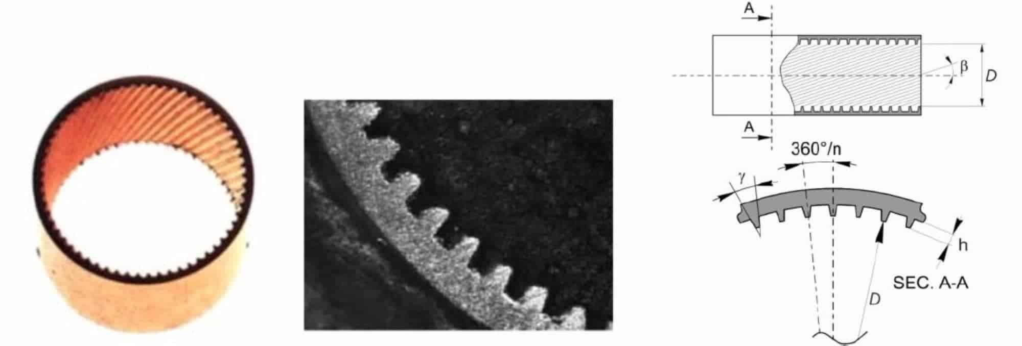
Photos of a microfin tube and its geometrical characteristics. (Cavallini et al., 2009).
Two photos of a microfin tube and a drawing are reported in the figure above. Microfin tubes are typically made of copper and have an outside diameter from 4 to15 mm, a single set of 50‐70 fins helix angle (ß) from 6 to 30°, fin height (h) from 0.1 to 0.25 mm, triangular or trapezoidal fin shapes with an apex angle (γ) from 25 to 90°; finally these tubes present an enhancement of the effective heat transfer area from 1.8 to 2.2 when compared to a smooth tube with similar inner diameter.
Heat transfer and pressure drop enhancements are partly due to the simple increase in the exchanging surface, due to the turbulence induced to the liquid film by the micro‐fins, and due to the surface tension effect on the liquid drainage.
Still there’s a question left to discussed about the use of enhanced surfaces to improve the heat transfer capabilities during both single and two phase flow inside pipes:
are those tubes necessary and convenient always?
The answer to this question might look very simple at first sight: we may answer quickly that everything that improves the heat transfer coefficients should be used in a well‐designed heat exchanger. On the contrary the use of microfin tubes involves several aspects of the heat transfer inside the heat exchangers, with pro and cons. As a result, the answer to this question it is indeed much more complicated, and needs to be deeply dicussed, which is going to be done below.
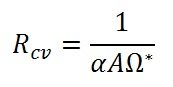
First of all, we have to recall the definition of convective thermal resistance; in fact, the heat flow rate exchanged in a heat exchanger, between two fluids at different temperatures, flows through the wall like an electric current passes through several electrical resistances connected in series.
Therefore, the thermal resistances are similar to the electric resistances; when several reisistances are connected in series, the total resistance is given by their sum. This means that if a resistance is much greater than the others, it can be considered dominant and the total resistance is almost equal to the greatest one. It is considered significantly dominant when it represents around 70‐80% of the total resistance. We can state that in a well optimized heat exchanger, the thermal resistances should be almost similar to each other, so that no one can be considered to be dominant. The convective resistance formula is the following:
Where ![]() is the heat transfer coefficient and
is the heat transfer coefficient and ![]() is the product of the heat transfer
is the product of the heat transfer
area and the surface efficiency (applicable when using extended surfaces). The subscripts I and O refer respectively to the Inside tubes side and the External Tube Side.
The overall thermal resistance is given by:
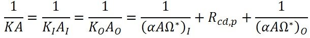
where Rcd is the conductive thermal resistance of the wall, which will be ignored in the following examples.
Now we can try to answer to the previous question.
Case I: considering a shell and tube heat exchanger, where some water flows through the shell side with a heat transfer coefficient equal to = 5000 W m -2 k-1, while different fluids flows inside the tubes: a condensing vapour ( = 5000 W m -2 k-1), a water flow rate ( = 2500 W m -2 k-1) and, finally, a water glycol mixture solution ( = 1250 W m -2 k-1).
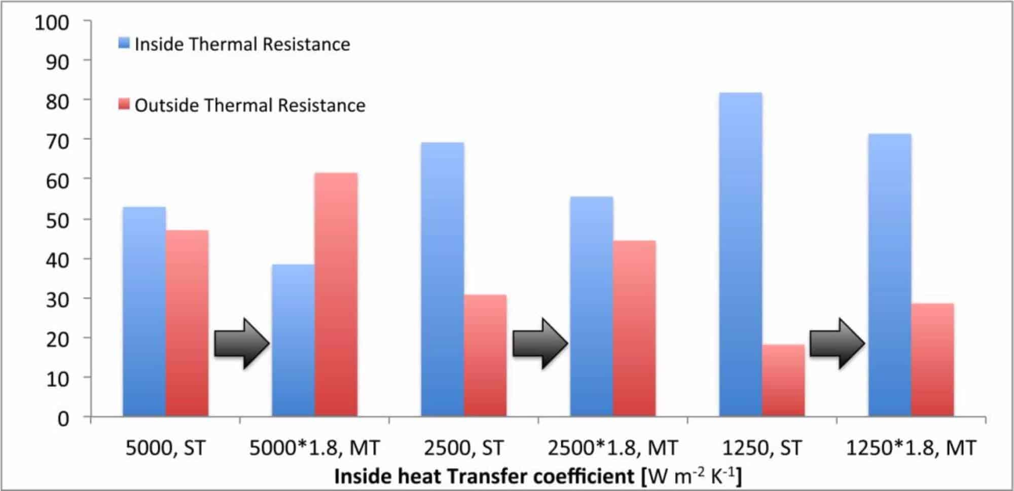
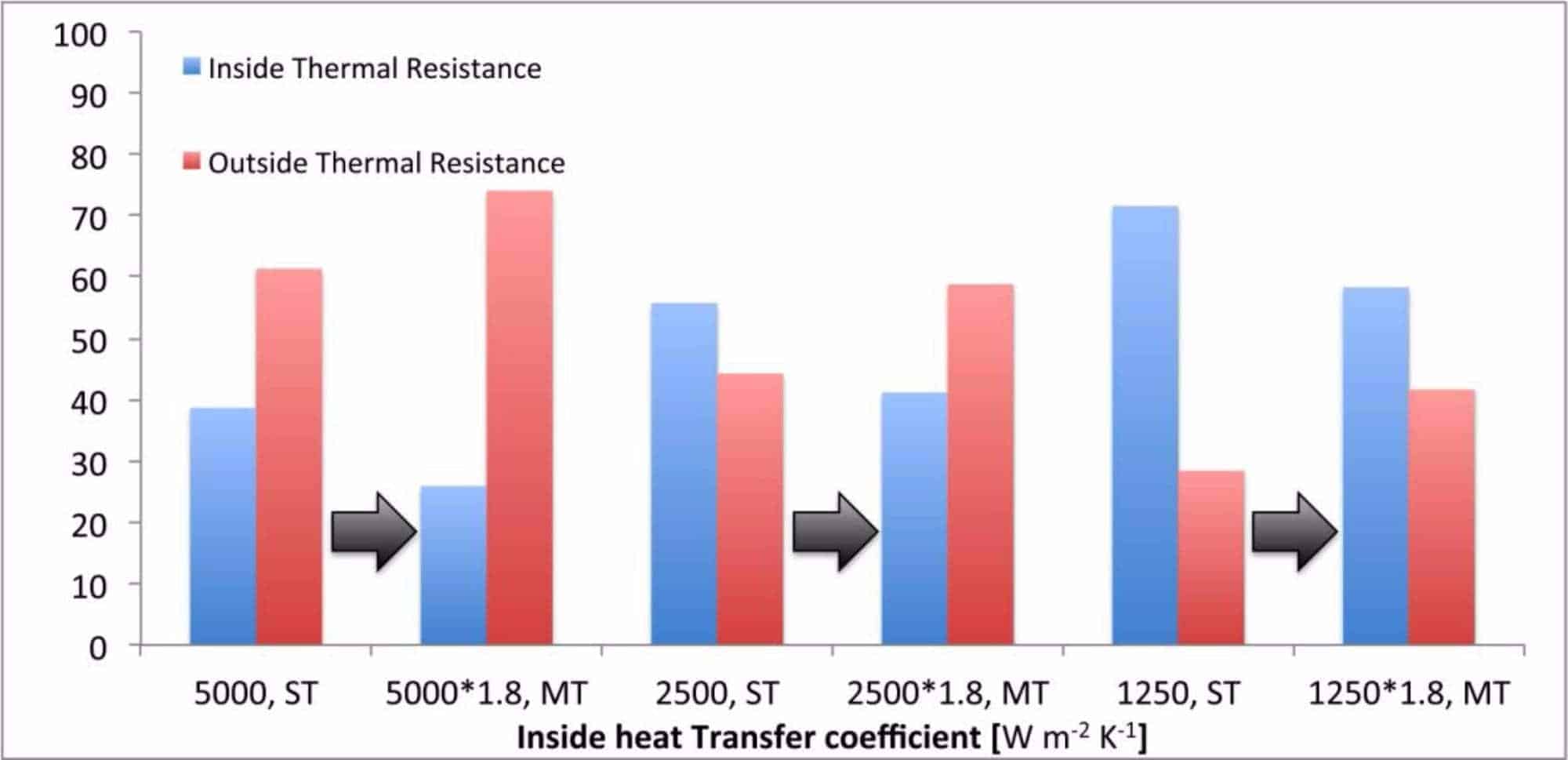
Case I: effect of the microfin tubes on the thermal resistance harmonization. Shell side heat transfer coefficient equal to 5000 W m‐2 K‐1. ST: Smooth tube; MT: microfin tube.
The results above permits to understand when a microfin tube should be used and when it is completely useless; in this case, we have considerd a microfin tube, which improves the inside tubes heat transfer rate by a 1.8 factor over the corresponding smooth tube.
Looking at the figure, when = 5000 W m‐2 K‐1 the heat exchanger is optimized (5000, ST) because the two thermal resistances are almost the same. In this case, the microfin tube should be avoided because the outside thermal resistance would become dominant (see 5000*1.8, MT).
When decreasing the internal heat transfer coefficient, it’s thermal resistance that becomes dominant. This means that the microfin tube becomes useful and important. In the above example, the use of a microfin tube changes the inside heat transfer coefficient passes from 2500 W m -2 k-1 (ST) to 4500 W m -2 k-1 (2500*1.8, MT) and the two thermal resistances can be considered almost equal.
The use of the enhanced surfaces permits to improve also the worst case above, when the of the smooth tube is very low (1250, ST). Even if the heat exchanger is not optimized, the microfin tube enhances the internal performance (1250*1.8,MT).
Case II: we consider a coil heat exchanger where the air side heat transfer surface has already been optimized using a louvered fins surface with A0/A1=21.
Considering also the three previous heat transfer coefficients examples on the tube side, the figure below shows the calculated thermal resistances.
Case II: effect of the microfin tubes on the thermal reistance harmonization. Air side heat transfer coefficient 150 W m‐2 k‐1 and A0/A1=21. St: Smooth tube; MT: microfin tube.
Considering the smooth tube, when = 5000 W m -2 k-1 (5000, ST), the air side thermal resistance can be considered dominant: so, the use of microfin tube is meaningless as highlighted in the figure (5000*1.8, MT).
When the decreases, the tube side thermal resistance quickly increases, making the use of the microfin tube necessary, as demonstrated by the (1250, ST) and (1250*1.8, MT) cases. The use of the microfin tubes permits to harmonize the thermal resistance leading to a more optimized heat exchenager design.
The above two simple examples permits to understand that the implementation of an enhanced surface, in order to improve the tube side heat transfer coefficients, must be deeply analysed in advanced. Sometimes the use of microfin tubes is definitely necessary but, in other cases, it can lead to a non‐optimized heat exchanger design.
References
- Fuje K., Itoh N., Kimura H., Nakayama N., Yanugidi T., Heat transfer pipe, US
- Patent 4044797, assigned to Hitachi LTD, 1977
- Cavallini A., Del Col D., Mancin S., Rossetto L., Condensation of pure and near‐azeotropic refrigerants in microfin tubes: A new computional procedure. International Journal of Refrigeration, vol. 32, p. 162‐174, 2009
Related topics:
- Microchannel: applications and perspectives
- Plain fins or louvered fins:which is the best configuration?
- Evaporator and condenser: co‐current or counter‐current?


